How can wind farm developers achieve best in class project CAPEX costs?
Similar to the strategy for achieving OPEX savings*, significant client involvement is needed; this time in the development and construction processes. Simply put – put the correct structure in place and savings will follow.
Developer Involvement
There are 3 principal involvement choices:
1) Passive (Financial investors) – minimum involvement in project managing technical issues i.e. accepting consultant’s deliverables with little discussion (provided main findings are in line with expectations)
2) Intermediate (Small developers with minor pipeline) – Increased involvement but with low priority on optimisations
3) Active (Larger developers with big pipeline) – Experienced in-house team who review thoroughly consultants/contractors deliverables and who are given scope to explore innovative optimisations from consultants and suppliers.
Active involvement requires more resources but if the owner puts this in place the door can be opened to significant optimisations.

Below I give my own experiences on how to put in place systems that will drive CAPEX efficiencies; some will produce direct and tangible savings, others will improve project management and help avoid painful client “u-turns” and frustrations for project stakeholders. (Note: I focus here on the post permit/auction phase where wind resource is already determined).
GIS system set-up (Extra Software Budget = € 10-30,000)
Engineering a wind farm requires collation of all necessary input data before design is commenced. This data is obtained from land lease agreements, previously conducted desk/ on-site surveys, building permits, suppliers requirements etc. Typically this information is spread over multiple reports and drawings and having a good “helicopter view” of the project is difficult using traditional “paper” methods.
Accordingly it is very worthwhile especially if developing a large portfolio to consider using a Geographical Information System (GIS) which can store all design input information on separate layers and into which the design information can be added at a later stage. This allows all designs to be cross checked easily against known restrictions.
→ Benefit: GIS maximises the potential for identifying and resolving any clashes at the early design stage as opposed to an expensive resolution during the construction period.
Existing Services Survey (Extra Typical Cost €500/WTG)
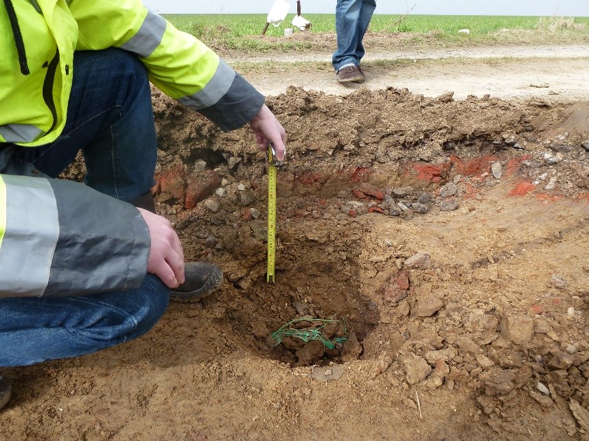
As a first step to locating underground and overground services (e.g. water, electricity, cabling, gas etc.) a request for information on existing services should be sent to known service providers who are known to operate in the vicinity of the wind farm. The routes of underground services should then be proven by excavating trial pits along the service routes. These routes and service depths need to be proven to avoid later problems.
On one project I was involved in a water pipe found at a different location than that indicated on “as-built” drawings required diversion at considerable cost and with significant impact on construction programme i.e. €25,000 and 3 months of negotiation and construction time by a the service providers contractor.
→ Benefit: Take uncertainty out of location of potential obstacles. Better to be safe than sorry….
High Quality Topographical Survey (Extra Cost <€500/WTG)
Although the Topographical Survey is often the lowest cost contract during the engineering phase that does not reduce its importance. It is critical to prepare a comprehensive and detailed scope and to ensure extent of survey is adequate for proposed design and, critically, will also cover any potential changes in access to WTG locations. As a rule of thumb survey 1 rotor diameter around WTG locations and along centrelines, edges of asphalt and road verges on access roads and any nearby embankments, services etc. More survey = more good data.
Defining a good specification, ensuring speedy access to the survey site and carefully monitoring survey activities and results maximises your return on contract costs. If the above rules are followed a one-shot survey should be possible which will avoid lost time and money if a resurvey is needed.
→ Benefit: Take uncertainty out of location of potential obstacles. Better to be safe than sorry….
Geotechnical Investigation with Hydrogeological Survey (Typical Cost €500/WTG)
Similar to the Topographical Survey the scope of this survey and the required findings need to be carefully considered. As a first step a desk study of the area to consider new and historical databases should be undertaken. Then at least 2 boreholes per WTG location should be conducted along with trail pits and soil sampling.
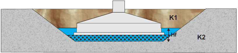
In addition depending on the location and soil characteristics (particularly for WTG locations with clay sub-strata) it may be wise to conduct a hydrogeological survey to determine water table levels and annual fluctuations. Modelling the maximum water table level may allow you to change the designation of foundation from full buoyancy to partial buoyancy design and thereby save €10,000+ per foundation. Again like the Topographical survey close monitoring of the survey should be allowed for to have a “one-shot” result.
→ Benefit: The Hydrogeological Survey gives greater certainty as to water levels which can lead to potential savings for foundation designs
Micrositing (Typical Cost €1-2,000/WTG)
The benefits of micro siting depend on both the permitting regime and the site characteristics. Significantly different opportunities present themselves on a flat site where minimal movement of permitted WTG location is allowable (e.g. France) versus a hilly site where movement of up to 50m is allowable (e.g. Sweden).
To make best use of the Micrositing efforts energy production comparisons and environmental impacts (noise etc.) along with optimisations related to civil engineering and WTG erection issues should be conducted for various WTG models.
→ Benefit: This ensures maximum value is obtained from the process and also allows good accountability of the decision making process if the project is later sold.
Conclusion
If the above steps are followed a very good basis will be in place to harvest CAPEX savings at the design and procurement phase. The steps require some additional investment by the developer but will lead to more certainty of design input data and easier exploration of optimisations.
In addition borrowing practices such as lean engineering from other industries can ensure the Capex budget is kept on a strict and controllable diet. More on that next time.
In the meantime feel free to add your comments below to expand the discussion and if you have any particular queries on wind farm development feel free to contact me on LinkedIn or email (fergal@forterenewables.com).
————————-
Fergal O’Mahony is Director of Forte Renewables and previously acted as the Engineering Manager for the development of a 1GW onshore project portfolio in 5 European countries. Forte is headquartered in Amsterdam and provide Engineering Management Services to wind farm developers in Europe and Brazil.
This article was posted originally at: http://www.forterenewables.com/blog/